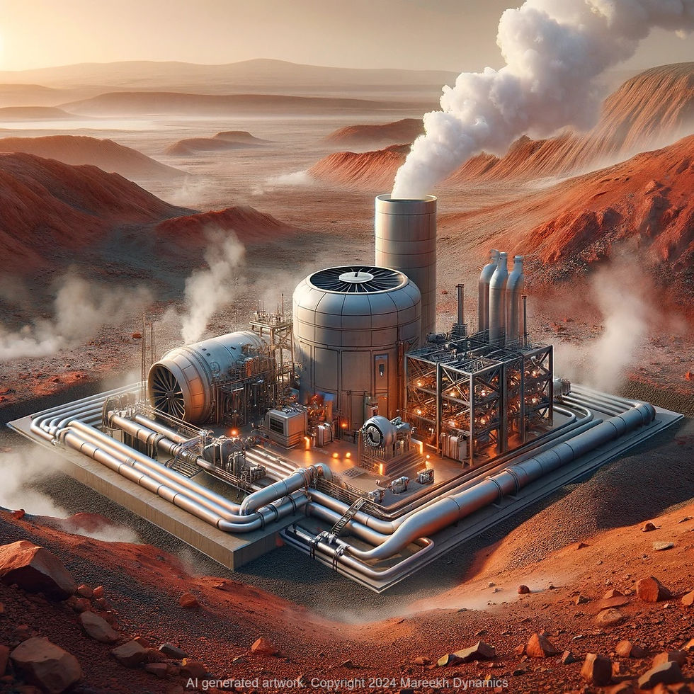
(An AI rendering of what Mareekh Process, a hybrid power generation concept for Mars, may look like.)
This is a follow up to our original post on the Mareekh Process which was incomplete pending further attempt at explaining its energy dynamics which we had tried to explain through the concept of Gibbs Free Energy deeply interwoven with the concept of entropy and enthalpy changes of the substrate (subsurface ice) and the product (steam at Martian atmospheric pressure) utilizing the very deep heat sink of the Martian atmosphere for its low pressure (0.6kPa) and temperature (average minus 60c).
I made the first mention of using Martian permafrost to generate steam and its utilization in running steam turbines on the Martian surface in my submission for the International Mars City State Design Competition in 2020 which was also published in the book 'Mars City States; New Societies for a New World’, (Chapter 3, MAREEKH. An introduction to Engineering, Economic and Social Perspective of Establishing a Human Civilization on Mars). In this chapter, I proposed sending heat down into the Martian permafrost using auxiliary sources such as solar and (limited) nuclear (RTGs or SMRs) to convert the permafrost into steam and extracting it to run a steam turbine on the surface to generate electricity. The basic idea was simple; using the very low atmospheric pressure on Mars to achieve explosive expansion of the steam to run the turbine. On Earth, the superheated steam in a steam turbine cannot expand beyond a certain level, as when it reaches its saturation temperature and pressure for the Earth’s atmosphere (1 bar and 100 degrees c), it would stall. In order to continue the expansion of this steam and extracting mechanical work from it, a surface condenser is used which creates a partial-vacuum (usually at 0.1 bar pressure, or 10kPa) through heat rejection to the exterior using water from external reservoir (usually a natural water body such as a lake or a river) that flows through hundreds of tubes inside the condenser and cools down the steam, condensing it in the process. Since the steam turbine is a closed space with no connection to the exterior, this condensation of water leads to the creation of a partial vacuum which drives the expansion of the steam inside the turbine from high-pressure to low-pressure turbine housing. The condensate is then recovered for reheating and thus the cycle continues. Nearly 40-50% of the heat energy content of the steam (originally provided to it by the burning of fossil fuel such as coal, or from a nuclear core) is rejected to the exterior using the surface condenser.
On Mars, the atmospheric pressure is already close to vacuum (0.6kPa). So, potentially no surface condenser is needed, not at least to achieve low pressure to drive the expansion of the steam, which will continue to expand explosively, and run the turbine until it reaches its saturation pressure and temperature in equilibrium with the Martian atmosphere, without needing to reject heat to the exterior in order to achieve this low pressure at the end of the turbine.
This extra mechanical work obtained without the expense of much heat content of the steam, and thus the input energy, is the core principle behind the Mareekh Process; our patented hybrid power generation concept for Mars, utilizing permafrost on Mars as a power source in the unique thermodynamic perspective of the Martian environment.
We have discussed in our previous blog that the conventional resources of energy for power generation on Mars are either extremely limited and unreliable (solar or nuclear), non-existent or are unharnessable (wind, tidal, geothermal, fossil fuel). A novel method for power generation must be developed on Mars to generate a massive amount of unlimited and clean energy for a permanent human settlement there, such as fusion energy, or the utilization of permafrost to run the steam turbines. Only that the technology to develop the latter already exists.
Understanding the working of Mareekh Process
Mareekh Process, utilizing the subsurface ice on Mars to produce steam and then using it to run turbine at Martian atmospheric pressure to extract a net energy raises many questions, including how it can be achieved, what are the thermodynamic principles behind its working and the energy output, and what is the source of this apparent ‘extra energy’. We will explore these questions as a walkthrough of our journey in designing of the Mareekh Process.
Designing the Mareekh Process
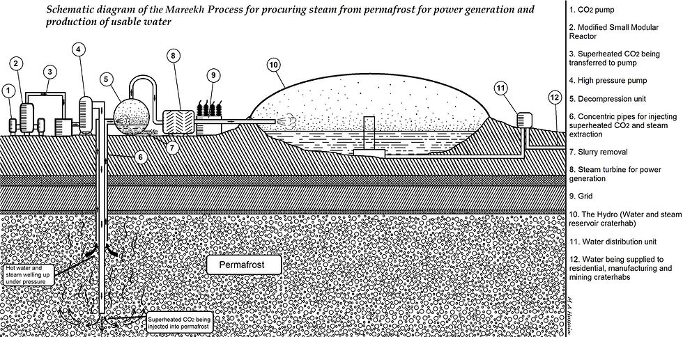
(The original (now redundant) concept of hydraulic fracturing of the subsurface permafrost to extract steam)
The initial concept was to inject heat using auxiliary power source such as solar or limited nuclear into the permafrost, melting it and then turning it into superheated steam, extracting this steam and using it to run a steam turbine at Martian atmospheric pressure. The heat transfer medium of choice was CO2, which is plentiful on Mars and is a tested heat transfer medium on Earth for many mining and industrial applications. The CO2 is heated and pressurized, and converted into superheated-supercritical Sh-Sc CO2, which is then injected into the permafrost.
The next step was to have the steam extracted (by some means) and released into a flash tank at a very low pressure where the superheated steam is flashed into saturated steam and a condensate. This process removes the impurities and clean steam is released into the turbine. The spent steam is released into a special purpose Craterhab with internal pressure of nearly 1 bar where the steam condenses into water for use.
There were few major problems with this rudimentary design. The biggest one was the loss of steam (and thus the input energy) underground as only a fraction of steam could be extracted in this way. The other major problem was the use of saturated steam to run turbines which is not suitable for power extraction purposes. The third major problem was the need to provide the latent heat of vaporization to convert the subsurface ice into steam. The input energy far exceeded the output energy in this rudimentary design.
So we had to think of some design iterations.
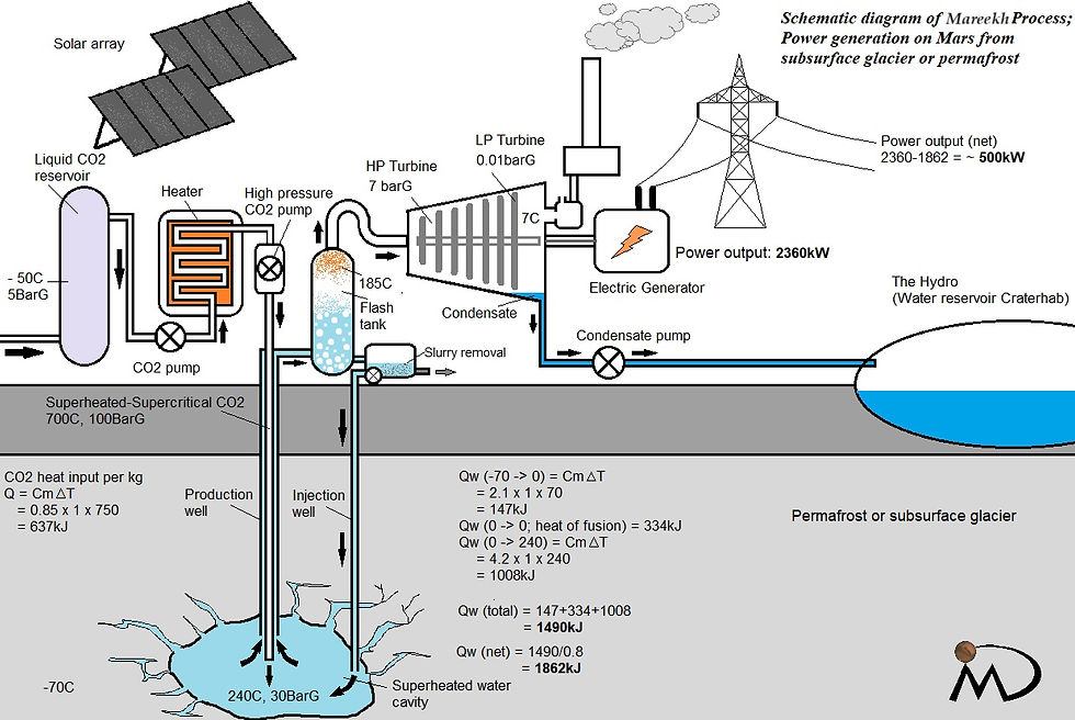
(Extracting superheated water and flashing in a flash tank (redundant). )
We figured out that heating the subsurface ice deep within the Martian surface, somewhere at a depth of 300m or so, at 30 bar gravitational pressure, will allow us to create a cavity of superheated water which can be extracted and flashed into a flash tank at a pressure lower than the deep water cavity but high enough to create steam to be released into the turbine. This design iteration would help prevent conversion of water directly into steam in the energy input process, saving the input of the latent heat of vaporization. But the problem was the saturated steam again. The hot water always flashes as a saturated steam when exposed to pressure below its saturation pressure for its temperature. Only a fraction of steam flashes in this manner and leaves the unflashed portion as a large amount of relatively cooler condensate. Flash steam cannot be pumped, because any amount of pressure to pump it forward will result in its condensation.
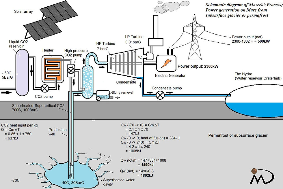
(Another iteration (redundant) considered feeding superheated water directly into the turbine)
In one design, we considered injecting superheated recovered water directly into the turbine. While saving heaps on the latent heat of vaporization, the problem of superheated water flashing into saturated steam remained.
One way of solving the problem of saturated steam is to superheat it. Unfortunately again the saturated steam cannot be easily pumped back into the system without having it condensed during this process.
This is where we thought of using supercritical water and a set of two feeder systems; one for the saturated flash steam, the Low Pressure Feeder System (LPFS), and the other for supercritical water, the High Pressure Feeder System (HPFS). Supercritical water exists beyond 374 degree c and 220 bar pressure where the water exists neither as a liquid nor steam. By further heating it well above this temperature and pressure at a constant volume (isochoric), the specific heat remains quite low, and evades the need for providing the latent heat of vaporization.
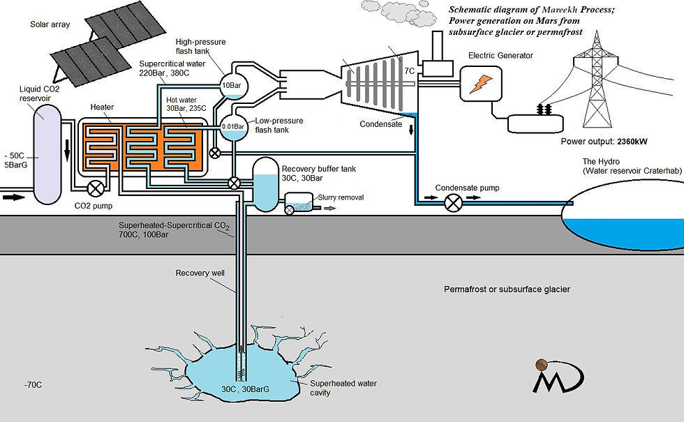
(A redundant iteration representing a LPFS and HPFS)
In the design with feeder systems, the subsurface ice is only melted enough to create a liquid water reservoir at 30 degrees c (at 30 bar for 300m depth) using the injected Sh-Sc CO2 at nearly 700c and 100 bar. The liquid water is recovered using a bidirectional turbine driven by the injected Sh-Sc CO2. The recovered water is stored in a buffer tank, connected to a slurry removal tank. A pre-calculated amount of water is pumped into the heater through LPFS to heat it up at 30 bar pressure and 233 degrees c to form subcritical superheated water. This water is then flashed into a flash tank maintained at 0.6 bar pressure. Here nearly 28% of this water is immediately flashed into saturated flashed steam at nearly 87 degree c, leaving a condensate behind at around 87 degree c. This hot condensate is pumped back into the LPFS for reheating. The flashing fraction of superheated water will be higher for lower flash tank pressures.
The condensate from the turbine itself (its formation will be discussed shortly) is pumped into the heater through a HPFS where it is isochorically heated at 300 bar pressure up to 550 degree c to convert into supercritical water which is free of any impurities and minerals, being a distilled condensate..
Both flashed saturated steam from LPFS and the supercritical water from HPFS are pumped through a low pressure flash tank and a high pressure flash tank.
This did not fix the problem of saturated steam being injected into the turbine. This also did not address the steam in LPFS flash tank at lower pressure to be pumped into the high pressure turbine where the pressure is aimed to be 2 bars.
We solved this issue by applying Venturi Effect in a combined injector for saturated steam from LPFS and the supercritical water from the HPFS and removed the HPFS flash tank altogether.
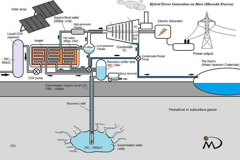
(Current iteration of the Mareekh Process, US patent 11,421,559 B1, showing a common injector for HPFS ScW and LPFS flash steam.)
This configuration solved the two major problems; injection of saturated steam in the turbine, and propagation of the saturated steam. The supercritical water at 550c from HPFS exits at an immense pressure of 300 bar, and superheats the saturated steam from LPFS, and its pressure drives the saturated steam towards the turbine through a powerful Venturi Effect. Through carefully adjusting the masses of the flash saturated steam from LPFS and supercritical water from HPFS, superheated steam at 195 degree c and 2 bar pressure can be created and injected into the turbine. Our calculations suggest flash steam from LPFS at 87c and supercritical water from HPFS at 550c in a ratio of 2:1 injected together into the turbine housing will create a superheated steam of 195 degree c. In our calculations, we have used the inlet steam pressure of 2 bars which can be achieved through the cross-section size of the high pressure turbine housing.
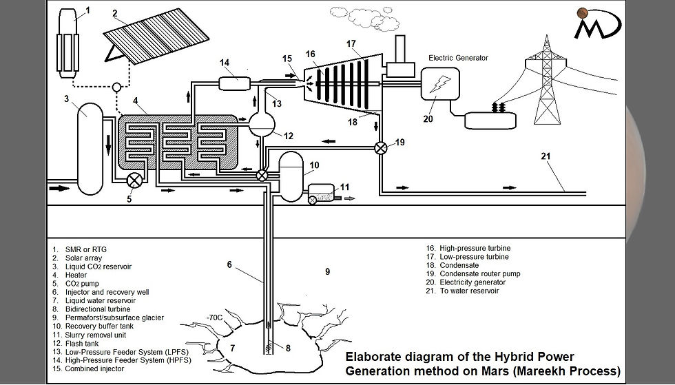
(A labelled diagram of the Mareekh process)
The steps involved from extraction of water to converting it into inlet steam in the turbine and power generation, to the extraction of it for reuse are as follows.
1. Heat injection
Heat is injected into the subsurface ice using CO2, readily available locally on Mars. The CO2 is heated under pressure inside an enclosed heater using auxiliary solar or limited nuclear such as RTG, and is pumped as a Superheated-Supercritical (ShSc) CO2 at 700c and 100 bar through an injection and recovery well into the permafrost or subsurface glacier with an estimated temperature of -70c and pressure of 30 bar which is the approximate pressure inside Martian crust at the depth of around 300m.
Sh-Sc CO2 not only serves as a good heat transfer medium, it also helps precipitate dissolved impurities and dirt and settles it in the bottom of the water cavity thus formed, deep inside the permafrost.
In our model, the temperature of the liquid water reservoir is maintained at 30C and pressure at 30 bar at a depth of 300m. 2. Water recovery
The injected Sh-Sc CO2 drives a bidirectional turbine near the deep end of the injection well. This helps pump the liquid water at 30 C and store in a very well insulated surface recovery buffer tank maintained at 1 bar.
The recovery buffer tank is where the recovered water is decarbonated and degassed, and CO2 recovered for reuse. The recovery buffer tank is also connected to a slurry removal system. 3. Low Pressure Feeder System (LPFS)
Its purpose is to create the bulk of saturated flash steam using low pressure of the Martian atmosphere. Though the pressure in the flash tank is maintained at 0.6 bar in our model.
Water from the recovery buffer tank at 30c and the condensate from the flash tank and the turbine at 86.5c and 6c is pumped into the LPFS to create superheated subcritical water at 233 degree c and 30 bar pressure. It is then released back into the flash tank.
In this tank at 0.6 bar pressure, nearly 28% of superheated water from the LPFS flashes into steam at 86.5c which is saturated. The rest of 72% will settle as condensate at the same temperature of nearly 86.5c, which is then recirculated in the LPFS as mentioned earlier.
The purpose of using a flash tank is to create the steam OUTSIDE the heat input assembly, in order to avoid giving the latent heat of fusion for its creation (which is massive, at 2256kJ/kg) and let the low atmospheric pressure do the job. Though the pressure inside the flash tank is 0.6 bar, which is ten times higher than the outside pressure of the Martian atmosphere, it is easier to maintain this on Mars than it can be on Earth. Even lower pressure such as 0.1 bar can be achieved and will create a larger fraction of flash steam, requiring even less amount of supercritical water to run the cycle but at the cost of reduction in the strength of the Venturi Effect and a cooler flashed condensate. 4. High Pressure Feeder System (HPFS)
The purpose of HPFS is to create supercritical water through isochoric heating and using it to heat the saturated flash steam from LPFS into superheated steam, and also to increase its bulk, before releasing it into the turbine through Venturi Effect.
The condensate from the turbine is used for the purpose of creating supercritical water as it contains little or no impurities as all.
The water in HPFS is isochorically heated to 550c at 300 bar pressure to circumvent the pseudo-boiling phase, thus evading the need for providing latent heat of vaporization yet again.
The supercritical water from LPFS is then injected into a common injector connected to the flash tank. The Venturi Effect from the injected supercritical water draws in the saturated flash steam at 0.6 bar pressure and mixes with it to create superheated steam. This superheated steam is then injected into the turbine using pressure from the HPFS at 300 bar.
5. The Turbine
Superheated steam at 195c and 2 bar pressure is released into the high pressure turbine housing.
The turbine is initially maintained at Martian atmospheric pressure of < 1kPa. The superheated steam adiabatically expands towards the low pressure turbine housing as in any steam turbine. This expansion of steam generates a flow which in turns moves the turbine blades at high speed.
As the steam moves through the turbine, it starts to cool down and a part of it continues to condense into water droplets.
The expansion and flow of the steam continues towards the low pressure turbine assembly until it reaches the end of the turbine assembly at 0.01 bar (1kPa) and 7 degree c.
In a sealed assembly, this process of steam expansion and flow will eventually stall.
On Earth, in order to achieve a partial-vacuum (0.1 bar or 10kPa), a surface condenser is attached which further cools down the steam in a diabatic process through heat loss to the tubes with flowing water in them, carrying and rejecting heat to the external heat sink in the process. This rejected heat can be up to 40-50% of the total energy of the inlet steam.
On Mars, the near-vacuum pressures can be achieved through an adiabatic process using a exit-control or pressure-control valve, which allows a small quantity of end-steam to exit to the exterior into the Martian atmosphere with a pressure of only 0.006 bar or 0.6kPa. This loss of mass of the end-steam (6-8%) causes the remaining end-steam in the last part of the turbine housing to expand. The end-steam is already saturated and is at its dew point, with much of it already condensed into water in the earlier parts of the steam turbine housing. This slight expansion of the cooled steam at its dew point causes it to further cool down to below its dew point for that pressure, causing it to immediately condense into water almost entirely, creating a near-total vacuum inside the low pressure turbine housing. The exit control valve now closes. More steam rushes in and as the pressure reaches above 0.01 bar (1kPa) the exit control valve opens again, letting 6-8% of the saturated steam out, causing expansion, cooling and condensation of the end-steam, and the cycle continues. In practice, the exit control valve may continuously remain open as this process of steam flow into the low pressure turbine housing, exit of a fraction of it to the exterior, and the expansion and condensation of the remaining steam will run as a continuous process.

(An AI illustration showing steam exiting into the Martian atmosphere causing adiabatic expansion and cooling of the remaining steam inside, forming condensate. Note the exit steam converting immediately into amorphous ice of very high entropy upon contacting the extremely cold Martian environment and settling to the ground)
Calculating the Power Output
The power output of a regular steam turbine is determined by the mass flow rate (m) multiplied by the enthalpy difference of the inlet (h1) and the end (h2) steam (or working fluid), which can be calculated by the formula;
P = m x (h1-h2)
For simplicity, our steam turbine calculations are based on 1.5kg/s of inlet steam flow, with the following parameters
Inlet steam:
Temperature: 195c, pressure 2 bar (200kPa)
End steam
Temperature: 7c, pressure 0.01 bar (1kPa)
Enthalpy of inlet steam: 2861kJ/kg
Enthalpy of end steam: 2514kJ/kg
Power output = 1.5 x (2861-2514)
= 1.5 x 347
= 520kJ/s or 520 kilowatts
However, one point that should be noted here is that a certain fraction of the end steam would have already condensed into water during its transit through the later part of the steam turbine, utilizing its latent heat of vaporization into expansion and running the turbine, and dropping its internal energy and thus enthalpy while condensing into water.
How much of this remaining steam reaches the end turbine in vapour form is hard to say as it depends upon the turbine design.
A analogous scenario on Earth is a back-pressure steam turbine with little or no condensation of steam (the steam being recovered for industrial applications). Working at Earth’s atmospheric pressure of 1 bar (100kPa), the power output will be;
Inlet steam:
Temperature: 195c, pressure 2 bar (200kPa)
End steam
Temperature: 100c, pressure 1 bar (100kPa)
Enthalpy of inlet steam: 2861kJ/kg
Enthalpy of end steam: 2676kJ/kg
Power output = 1.5 x (2861-2676)
= 1.5 x 185
= 278kJ/s or 278 kilowatts
However in a condensing steam turbine, all of the steam in the low-pressure turbine condenses into water by rejecting a large amount on latent heat of vaporization through surface condenser, resulting in very little enthalpy of the condensate. Replacing the h2 in above equation with the enthalpy of the condensate will yield a very large power output.
Enthalpy of condensate at 45C and 0.1 bar (10kPa) pressure (Earth application): 188kJ/kg
Power output = 1.5 x (2861 - 188)
= 1.5 x 2673
= 4010kJ
During this process, the latent heat that was released while condensation was almost entirely lost to the exterior through the surface condenser, which can be calculated as:
Latent heat of vaporization = 2256kJ/kg x 1.5kg = 3384kJ
4010 - 3384 = 626kJ/s or 626 kilowatts
While on Earth, the rapid and effective expansion of the steam requires creation of a partial vacuum in the low pressure turbine housing of the steam turbine which is roughly 0.1 bar or 10kPa, but this is achieved at the expense of the internal energy (and enthalpy) of the steam which must be rejected to the exterior in order to achieve a continuous cycle of steam expansion, flow, and condensation for recovery.
On Mars, it is an altogether different story. Martian atmosphere is already at 0.006bar (0.6kPa). No surface condenser is required to achieve partial vacuum in the last part of the turbine. All that is needed is a small aperture open to the exterior. In our design, this aperture is guarded by a pressure- or exit-control valve, to control the flow of steam to the exterior, thus maintaining 0.01bar (1kPa) or any desired pressure in the low pressure turbine housing. This leads to the continuous expansion, flow and cooling of the steam throughout the turbine assembly.
Losing a small quantity of steam to the exterior has one more advantage. Letting a small fraction of steam (6-8%) escape to the exterior results in adiabatic expansion and cooling of the remaining steam which is already at its dew point, resulting in its rapid condensation, without any loss of heat. All that is lost is a small mass of steam and the enthalpy contained within it. This cooling and condensation of the end-steam is what is responsible for the maintenance of 0.01 bar pressure inside the low pressure turbine housing, which is constantly being replenished by the incoming steam which in turns gives up a small fraction of its mass to the exterior, and thus cooling and condensing itself, leading to a continuous cycle governed by the exit control valve.
One may ask the question as to where the latent heat of vaporization goes during the condensation of the steam in the low pressure turbine housing in the Mareekh Process?
To understand this, we must go a few steps back into the turbine housing,
In the steam turbine in the Mareekh Process, the steam from the higher pressure section of the turbine housing keeps expanding and rushing towards the low pressure turbine maintained at 0.01 bar pressure, or near vacuum. This expanding steam exerts work on the turbine blades in its way and uses up its latent heat of vaporization during this process. During this expansion process, it keeps on cooling down and a part of it continues to condense. If this steam condenses completely into water before reaching the low pressure turbine housing, no further steam will enter the last part of the turbine, thus shutting the exit control valve and stalling the process. To continue moving as steam, it requires lower pressure ahead of it with lower saturation temperature, while continuing to impart work on the turbine while expanding. This is facilitated by the input of energy in the form of latent heat released during the condensation process of the steam ahead of it, and so on, and continues to transfer this latent heat to the turbine blades as work during its expansion. In other words, the latent heat released during the condensation process of the end steam in an adiabatic process, actually is utilized to keep the incoming steam in an expanding vapor form instead of condensing, in a continuum of heat transfer ‘upstream’, and translating into work. This results in steam rushing in to replace the vacuum created by the condensing steam, and driving the turbine in its path. This is my understanding of what happens to the latent heat of vaporization released during the adiabatic condensation of the end-steam. Here a point should be noted that when we say ‘adiabatic expansion’, we only talk about the 92-94% of the steam that hasn’t exited through the exit-control valve. For the steam that has escaped, it exits with all its mass, energy and enthalpy; a sacrifice that is done to achieve the continuous running of the Mareekh Process. This enthalpy must be subtracted from the net power output of the Mareekh Process.
It can be put together in another way.
The design of Mareekh Process is a hybrid between a condensing steam turbine and a back-pressure steam turbine. In latter, the steam is not condensed as it is extracted in steam form for industrial use. It has lower efficiency and power output due to less enthalpy drop than a condensing turbine. In the Mareekh Process, there is no condenser just like the back-pressure turbine, but the steam is made to condense like the way it is achieved in a condensing turbine, by utilizing adiabatic expansion and cooling driven by the extremely low atmospheric pressure and partial steam loss. Mareekh Process will achieve much higher power output than either of these turbines through condensation and much greater steam expansion, just like a condensing steam turbine, but through losing 6-8% of its mass and energy, against a whopping 40-50% energy loss to the exterior through surface condenser. The enthalpy drop achieved in the Mareekh Process is even higher through achieving ten times lower pressure in the low pressure turbine housing (0.01bar or 1kPa) than achieved by a typical surface condenser (0.1bar or 10kPa), in exchange of a small fraction of steam into the Martian atmosphere.
The adiabatic expansion and condensation of end-steam due to small mass loss to the exterior will increase the power output of a steam turbine, especially in a unique environment like Mars, by involving several thermodynamic principles. The perceived increase in power output in Mareekh Process, when compared to a conventional back-pressure turbine under these specific circumstances, can be attributed to a few key factors:
Enhanced Efficiency of Expansion: The continuous loss of a fraction of the steam's volume enhances the adiabatic expansion of the remaining steam. This process will increase the efficiency of the expansion process by reducing the partial pressure against which the steam expands. In simpler terms, as steam loses mass to the exterior, the reduced volume of steam within the turbine can expand more rapidly due to less resistance, converting thermal energy into mechanical work more efficiently.
Lower End Pressure: The continuous mass loss could lead to a lower pressure at the exhaust of the turbine. In a typical turbine, the efficiency of energy conversion increases as the difference between the inlet and outlet pressure increases. By effectively lowering the exhaust pressure through mass loss, the turbine operates across a larger pressure gradient, potentially increasing the work done during expansion.
Utilization of Latent Heat: The condensation of steam within the turbine, as a result of adiabatic expansion, releases latent heat. This release of latent heat occurs at a lower temperature due to the rapid expansion and reduced pressure, which might, under certain conditions, be more effectively converted into mechanical work than if the steam remained fully gaseous throughout the turbine.
Source of Extra Power: The "extra" power generated in this scenario comes from the enhanced conversion efficiency of thermal energy to mechanical work. By losing mass to the exterior, the system effectively lowers the back-pressure and allows the remaining steam to expand more, which could lead to a more efficient conversion of the steam's enthalpy to mechanical energy. This process leverages the thermodynamic principle that work done by a system (in this case, the turbine) is maximized when the expansion process is optimized to utilize the available thermal energy more fully.
Considering enthalpy drop as a result of adiabatic expansion of steam and condensation through mass loss and cooling, the power output can be calculated (using Steam Turbine Calculator) as: [Link: https://web1.hszg.de/thermo_fpc/]
Inlet parameters:
Flow rate: 1.5kg/s
Inlet steam: 195c, 2 bar
Outlet steam: 7c, 0.01bar → adiabatic expansion and condensation through mass loss and cooling → Condensate at 6c and 0.01bar
Power output = mass flow rate x (Enthalpy of inlet steam - enthalpy of condensate)
=1.5 x (2861 - 25)
= 1.5 x 2836
= 4253kJ
Subtracting enthalpy of exiting steam (0.1kg/s): 4253 - 251 = 4002kJ ~ 4000kJ
It can also be verified in another way:
End-enthalpy = Enthalpy of the condensate (<6c and 0.01bar) + Dryness fraction x [Enthalpy of steam (7c, 0.01bar) - Enthalpy of condensate]
The dryness fraction of the end-steam due to adiabatic expansion from mass loss to the exterior is essentially 0 as it rapidly expands and cools and condenses completely.
Using IRC calculator
End-enthalpy = 25kJ/kg + 0 ( 2514 - 25)
= 25kJ/kg
Power output = mass flow rate x (Enthalpy of inlet steam - enthalpy of condensate)
=1.5 x (2861 - 25)
= 1.5 x 2836
= 4253kJ
Subtracting enthalpy of exiting steam (0.1kg/s): 4253 - 251 = 4002kJ or ~ 4000kJ
So in principle, 1.5kg steam at 195c and at 2 bar pressure, expanding against a pressure of 0.01 bar pressure at 7c and condensing to 6c will generate around 4000kJ of power per second inside the Mareekh Process.
The amount of energy required to generate1.5kg superheated steam at 195c and 2 bar pressure from subsurface ice at -70c will be
E1 = (Ice -70 --> 0c) + (Melting of ice) + (Heating to 100c) + (Vaporization) + (Heating to195c)
=(460 x 1.5) + (334 x 1.5) + (3.5 x 1.5 x 100) + 2256 + (2 x 1.5 x 95) = 690+500+525+2256+285
= 4256kJ
A condensing steam turbine on Earth with the same inlet parameters will work between pressure ranges of 2 bar to 1 bar, with further extension of the low pressure to down to 0.1 bar (10kPa) by rejecting 40-50% of the heat energy to the exterior using a surface condenser.
Calculating direct power output of such a condensing steam turbine on Earth using the above inlet parameters and the Earth based outlet parameters using condenser:
Inlet parameters:
Flow rate: 1.5kg/s
Inlet steam: 195c, 2 bar
Outlet steam: 46c, 0.1bar → Surface condenser → Condensate at 45c and 0.1bar
With these parameters, the power output of such a condensing steam turbine on Earth will be:
Power output = Mass flow rate x (H1-H2) - (0.4 x E1) where H1 is the enthalpy of inlet steam, H2 is the enthalpy of the condensate, and the rejected heat fraction is 0.4 = 1.5 x (2861 - 188) - (0.4 x 4256)
= 1.5 x 2673 - 1702 = 2307 kJ
Calculating the energy input in the Mareekh Process
Now lets calculate the energy required to generate 1.5kg steam at 2 bar pressure using the Mareekh Process.
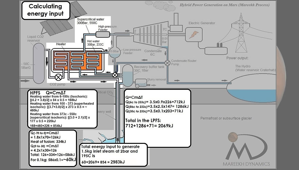
(Layout of the Mareekh process with breakdown of the energy input)
In the running of the Mareekh Process solely for the power generation, the amount of water in the system that needs replenishing constantly is only the amount that is lost into the Martian atmosphere. (But it will be higher if any amount of condensate is redirected to the Hydro; the water reservoir Craterhab, for human consumption). In our calculation, it is 0.1kg/s that needs to be replenished. This is the amount of water that is recovered from the subsurface liquid water reservoir every second, which in turn is the amount of ice that is melted by injecting the subsurface ice with ShSc CO2. Rest of the water that is being recirculated is from these sources (per second).
LPFS: - 2.5kg condensate from the flash tank- 0.9kg condensate from the end steam in the turbine- 0.1kg water from the recovery buffer tank.
HPFS:- 0.5kg condensate from the end steam in the turbine.
The energy required to form superheated steam at 195c and 2 bar pressure in this configuration is needed in these steps:
Recovery
To heat up 0.1kg ice from -70c to 0c: 12.6kJ
To melt ice at 0c to water at 0c: 34kJ
To heat up water at 0c to 30c: 12.6
Combined: ~60kJ
LPFS:
To heat up 0.9kg turbine condensate from 6c to 233c: 712kJ
To heat up 2.5kg flash tank condensate from 86c to 233c: 1286kJ
Tio heat up 0.1kg water from recovery buffer tank from 30c to 233c: 71kJ
Combined: 2069kJ
HPFS:
Heating water from 6-100c (Isochoric): [(4.2 + 3.8)/2] x 84 x 0.5 = 168kJHeating water from 100 - 373 (superheated isochoric): [(3.7+3.0)/2] x 273 x 0.5 = ~460kJHeating water from 373c - 550 (supercritical isochoric): [(3.0 + 2.1)/2] x 177 x 0.5 = 226kJ
Combined: 854kJ
Grand total: 60+2069+582 = ~ 2983kJ
Net power output in Mareekh Process:
Output - input = 4000kJ - 2983kJ = 1017kJ/s or 1017 kilowatts
So the net power output in Mareekh Process is 4000kJ from injecting superheated steam at 195c and 2 bar pressure compared to the energy input of 2983kJ. Apparently a surplus of 4000-2983 = 1017kJ is being obtained per 0.1kg conversion of ice into water to make up for the 0.1kg steam lost into the Martian atmosphere. Considering heat losses in the subsurface ice (though ice has some good insulating properties, there would still be heat loss in the ice surrounding the water cavity) and in the equipment, we can round it off to 800kJ/s or 0.8 megawatt.
This is a hugely positive number, as if the subsurface ice is acting as a fuel. So what is going on here?
The answer lies in the design of the Mareekh Process itself. First thing is the use of supercritical water formed isochorically in the HPFS to use as the heating and bulking medium for the saturated flash steam from LPFS, thus avoiding the pseudo-boiling phase of it by a huge margin, and keeping the specific heat very low [REF: Isochoric heat capacity of supercritical water].
Another key feature of the Mareekh Process is the complete avoidance of phase conversion of water into steam in any of the energy input steps , including the feeder systems, letting low pressures of the Martian atmosphere facilitate the formation of steam, thus saving on the provision of latent heat of vapourization.
But this is not enough to explain the apparent ‘excess’ energy we are getting, essentially utilizing the subsurface ice as fossil fuel.
Calculating Gibbs Free or Available Energy of the conversion of ice into steam and then undercooled vapor and condensate in the Martian atmosphere in the Mareekh Process is not simple, due to many different phase-change reactions and overlapping pathways. We can however simplify this process using example of a single phase change pathway, calculate the spontaneity of the process on Mars, compare it with that on Earth and estimate the difference. Here it should be noted that Gibbs Free Energy is not a quantitative figure but rather qualitative, and denotes the direction of spontaneity and its magnitude only.
In this example, we can assume that we are converting subsurface ice on Mars at -70c and under 30 bar pressure, into superheated steam at 195c and 2 bar pressure and then releasing it into Martian atmospheric conditions in a steam turbine maintaining 0.01bar pressure at 7c using an exit control valve.
Here are the values of enthalpy and entropy for Mars based and Earth based scenario for comparison.
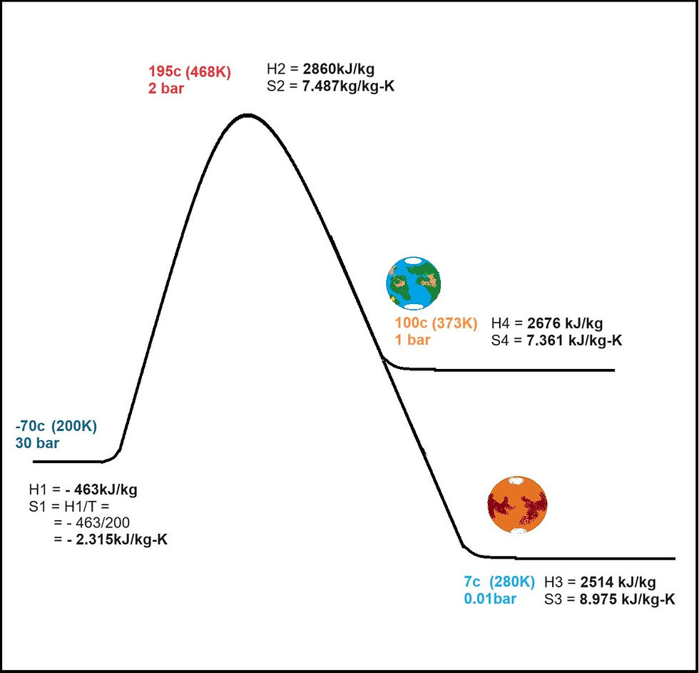
Using these values to calculate the Gibbs Free Energy of the conversion of subsurface ice on Mars through its conversion into steam and then releasing it into Martian conditions and also Earth conditions for comparison.
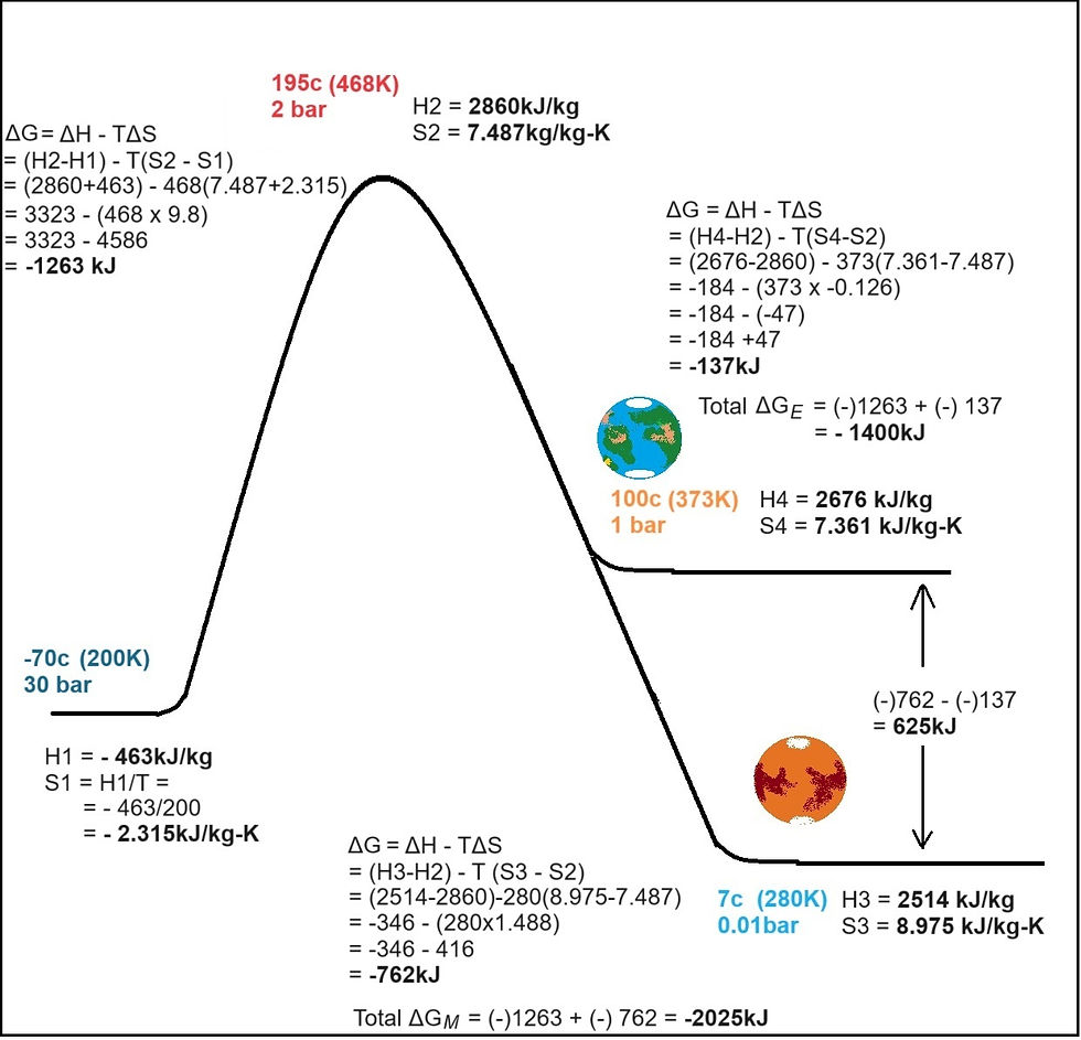
(Calculating and comparing the Gibbs Free Energy of the phase changes from ice to atmospheric steam on Mars and Earth)
Here it is clear that this process is far more spontaneous on Mars than it is achievable on Earth, giving out much more energy in the process with a difference of 625kJ on Mars more than that on Earth.
This equation does not demonstrate a net energy gain on Mars, because of the nature of the conversion, creating steam at 195c which requires a huge amount of latent heat of vaporization.
In Mareekh Process, there are two key differences:
No conversion to steam in any of the ENERGY INPUT steps (so no input of latent heat of vaporization)
Utilization of supercritical water formed through isochoric heating
This has huge implications. Mars has more than a hundred times lower atmospheric pressure than Earth. This enables explosive formation of large quantities of steam in the Mareekh Process from superheated water when exposed to low pressure facilitated by the low Martian atmospheric pressure. The rest of the cooled condensate is recovered for superheating. This saves a large amount of input energy which otherwise could be consumed in steam formation in the form of latent heat of vaporization.
Another feature is the use of supercritical water. When water is heated to beyond supercritical temperature and pressure (>>374c and >>220bar) in a fixed volume vessel (isochoric), the specific heat for this transformation remains very low (2.1kJ/Kg-K). This supercritical water later helps convert saturated flash steam into superheated steam and helps pump this superheated mixture into the turbine through Venturi Effect due to its pressure.
In Mareekh Process running on Mars, we are able to create steam without giving the latent heat of vaporization, which is not possible on Earth. To achieve a parity between Earth and Mars based scenarios, lets try to explain this apparent paradox using a direct steam turbine calculation, but completely using supercritical water both on Mars AND Earth, through Isochoric formation instead of superheated steam which would otherwise require input of latent heat of vaporization.
Energy required to form 1.5kg supercritical water at 550c at 300 bar pressure through isochoric means from subsurface ice at -70c and 30 bar pressure both on Mars and Earth is:
Ice (-70 to 0): 1.8 x 1.5 x 70 = 190kJ
Melting of ice (latent heat of fusion): 334 x 1.5 = 500kJ
Heating water from 0-100c (Isochoric): [(4.2 + 3.8)/2] x 100 x 1.5 = 600kJ
Heating water from 100 - 373 (superheated isochoric): [(3.7+3.0)/2] x 273 x 1.5 = 2130kJ
Heating water from 373c - 550 (supercritical isochoric): [(3.0 + 2.1)/2] x 177 x 1.5 = 677kJ
Total: 4097kJ
Calculating power output through a steam turbine on Mars: (direct method using US Dept of Energy calculator)
Inlet steam parameters:
Flow rate: 1.5kg/s
Supercritical water 550c at 300 bar(supercritical fluid) → 401c at 2bar (superheated steam) End steam parameters: 7c at 0.01bar → 6.6% mass loss through exit control valve → Adiabatic expansion and cooling → 6c condensate at 0.01bar
Energy output (using enthalpy drop between inlet and outlet): 4880kJ
Subtracting the enthalpy of exit steam: 4880 - 251 = 4630kJ
Net energy output: 4630 - 4097 = 533kJ
It seems like phase conversion of subsurface ice on Mars into vapour in the extremely thin Martian atmosphere does indeed give out a net energy output.
In order to further verify the seemingly counterintuitive phenomenon of getting an excess energy from ice, we need to replicate this on an Earth based scenario.
While on Mars, the condensation of the end steam in Mareekh Process is achieved through adiabatic expansion via mass loss containing roughly 6% of the input energy, on Earth the same is achieved through surface condensers via 40-50% energy loss to the exterior using a surface condenser, achieving around 0.1bar pressure inside the turbine.
Lets run these numbers for an imaginary steam power plant on Earth running on supercritical water based on the following parameters:
Inlet steam parameters:
Flow rate: 1.5kg/s
Supercritical water 550c at 300 bar(supercritical fluid) → 401c at 2bar (superheated steam)
End steam parameters: 46c at 0.1bar → 40% energy loss through surface condenser → condensation → 45c condensate at 0.1bar
Energy output (using enthalpy drop between inlet and outlet): 4670kJ
Subtracting energy loss through condenser: 4670 - (0.4 x 4097) = 3031kJ
Net energy output: 3031 - 4097 = - 1065kJ
So as we can see, while on Mars there is a net energy gain, on Earth, there is net energy loss when running a steam turbine from the same input parameters using supercritical water from subsurface ice.
In the Mareekh Process, the input fluid in the steam turbine would be a mixture of supercritical water and saturated steam, forming superheated steam at the turbine inlet. The main reason is to ensure safety of the handling and mitigate the risks associated with using supercritical water in high quantities.
So why is the Martian ice acting like Fossil fuel!
And here lies the potential answer.
Ancient entropy disequilibrium
The keyword here is Entropy.
We believe that the apparent surplus energy output in Mareekh Process is due the following two reasons:
1. Very low unbalanced transitional entropy:
Ice Formation and Structure: During the Martian wet era, the atmospheric moisture trickled underground as water. With the loss of atmosphere and the resulting global cooling on Mars, the subsurface water froze over, compacted under its own weight and the weight of the ground above, transforming into firm and solid glacial ice and permafrost. This ice forms a highly ordered crystal lattice, which is a manifestation of its low translational entropy. The molecules in the ice are arranged in a regular pattern and have limited freedom of movement, especially in the deeper layers where the ice is oldest and pressure is highest.
Unbalanced Entropy: At the time of formation of water on Mars and its accumulation under the surface, it was in thermodynamic equilibrium with the atmosphere above. As Mars lost its atmosphere, and the underground water froze, it created a thermodynamic environment with a much higher level of disorder and potential for energy exchange. The translational entropy of the deep glacial ice is unbalanced with its surroundings because it represents a state of lower entropy (more order) compared to the higher entropy (less order) of the surface conditions or the adjacent environment. This contrast is driven by the stark differences in temperature, pressure, and molecular mobility between the deep ice and its surroundings. 2. The deep heat sink of the Martian atmosphere and work extraction:
The second law of thermodynamics implies that for work to be extracted from a system, the total entropy of the system plus its surroundings must not decrease. A deep heat sink facilitates this by allowing the system to expel heat (and thus increase its entropy) more effectively, maintaining the overall direction of entropy increase while still converting part of the heat into work. Essentially, the deep heat sink acts as an effective repository for the entropy produced during the work extraction process, thereby aligning with the second law.
The Martian atmosphere can act as a very deep heat sink in relation to the subsurface compact ice, primarily due to the thinness of the atmosphere and the low temperatures prevalent on Mars. This scenario significantly impacts the translational entropy of subsurface ice and the potential for work extraction or energy transfer processes on the Martian surface.
This phase transition from subsurface ice to the atmospheric steam increases the entropy of the system, as the molecular disorder of steam is much higher than that of solid ice. When this steam is allowed to expand in a controlled manner, such as through a turbine or a piston, work can be extracted from the process.
After the steam has done work by expanding, it needs to be cooled back into a liquid or solid state to complete a cycle (in a theoretical thermodynamic cycle such as the Rankine cycle). The Martian atmosphere, being cold and thin, could theoretically serve as a heat sink for condensing the steam back into water, depending on the ambient temperature and the system's design.

(Entropy comes in several forms and has several implications. This huge boulder at the edge of the Grand Canyon was once on a level ground some 50 million years ago with no ability to do work and was in an equilibrium with its surroundings. The canyon is now acting as a sink, so that if the rock is nudged slightly, it will roll down the canyon and generate a lot of work on its surroundings)
The white gold on Mars
Mars lacks conventional resources for power generation including poor and unreliable solar power, no wind or tidal power, no known geothermal or radioactive reserves, and no organic fossil fuels. This is a major limitation for establishing a large-scale surface colony on Mars due to its very large power requirement for sustenance. The vast reserves of subsurface glaciers on permafrost on Mars owing to the ancient entropy imbalance may serve as a primary fuel source ready to be harnessed for an unlimited amount of clean energy.
Conclusion
Our patented Mareekh Process offers an alternative viewpoint in solving the power conundrum on Mars through in-situ resource utilization of the subsurface ice on Mars in current technology to harness its potential as a valuable power generation resource through the unique thermodynamic attributes of the Martian environment.
Resources:
US Patent and Trademark Office (USPTO). Patent Public Search. Publication No. 11421559 https://ppubs.uspto.gov/pubwebapp/static/pages/ppubsbasic.html
Steam Turbine Calculators https://www.codecalculation.com/htm/calculate/mechanical/engines/steam-turbine-performance/ https://www5.eere.energy.gov/manufacturing/tech_deployment/amo_steam_tool/equipTurbine
Engineering Thermodynamics - A Graphical Approach by Israel Urieli Part 1 - Introduction to the First and Second Laws of Thermodynamics, Chapter 4 https://people.ohio.edu/trembly/mechanical/thermo/
Properties Of Ice and Water Vapour at Low Temperatures - Chempro Gujarat India
AI illustrations. ChatGPT4: chat.openai.com
Thermodynamic properties of water and steam: https://irc.wisc.edu/properties/ https://web1.hszg.de/thermo_fpc/
Using Steam Tables to Determine Power Output of Steam Turbine https://www.youtube.com/watch?app=desktop&v=PVDfHZRqzcE

Kommentit